|
|
|
Categories
|
|
Information
|
|
Featured Product
|
|
|
 |
|
|
There are currently no product reviews.
 ;
Thanks you very much for this "hard to find" service manual.
Will help a lot in repairing this receiver.
;
Thanks you very much for this "hard to find" service manual.
Will help a lot in repairing this tuner.
;
I have this hi-fi system for a long time and I need to repair some things. Founding this manual will be very helpfull :)
 ;
It is pretty good. The schematics were covered all components, the manual also provide the parts list . It's useful for the trouble shooting.
;
Very fast service, best quality of the service manual and the schematics
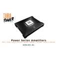
1Channel Automotive Amplifier
Controls and Connections
BP-300.1
R
R
INPUT LEVEL
LPF FREQ
BASS BOOST
+
R
HIGH LEVEL
-
L
+
+
R
HIGH LEVEL
-
L
+ 4V
.
250mV
.
32Hz
.
320Hz
.
.
0dB
+6dB
.
L FRONT INPUTS
L REAR INPUTS
BP300.1
8
1
5
6
7
FUSE 20Ax2
-
+ SPEAKER OUTPUTS
-
+ +BATT REM POWER GND
2
3
4
Controls and Connections
1. It allows left and right input channels to be connected to be amplifier using RCA plugs. 2. Speaker Output Connector - Connect speaker wiring to these connectors. See wiring instructions on page 4 for more information. 3. Fuse - Two 20 Amp ATC type Fuses. 4. Power Connection for 12V+, GND and REM connections for power wires. See wiring instructions on page 4 for more information. 5. Input-Level Control - Adjusts input sensitivity for pre-amp level and speaker level inputs. 6. The electronic crossover is a 12dB/oct. Low pass filter which can be Set at any frequency between 32Hz and 320Hz. 7. The bass boost control will provide up to 6dB of boost at 50Hz.
8. It allows left and right input channels such as high leve speaker output signals to be the amplifier.
Mounting the Amplifier
The JBL BP Series amplifiers can be mounted in virtually any location inside the vehicle. However, make sure to keep the amplifier away from heater vents or ducts. 1. At the chosen site, use the amplifier as a mounting template and mark the locations of the four mounting holes. 2. Drill a small pilot hole at each marked location. 3. Mount the amplifier and securely tighten the mounting screws.
3
|
|
|
> |
|